Measuring system
The measuring system has the following main parts:
- HAMAMTSU multiplier module
- Carousels with filters
- Lens case
- ARDUINO-based control system and PC communication
HAMAMTSU photomultiplier module
The module HAMAMATSU H10722-20 contains, in addition to the multiplier itself, a controlled high voltage source for dynodes and photomultiplier signal amplifier
0 - 4 V. The module requires a power supply +/- 5V, consumption is not large (approx. 10 mA). The voltage on the dynodes is controlled by applying a control voltage of 0 - 1.1 V.
The manufacturer recommends a control range of 0.5 - 1.1 V, when the sensitivity of the photomultiplier changes by approximately 1 order to 0.2 V. Below 0.5 V, the sensitivity drops sharply to zero.
The output voltage (signal) is conducted by a coaxial cable to suppress interference. The module also provides an exact reference voltage of 1.2 V, if the user would like to obtain
the control voltage by passive potentiometer. The signal from thermoelectrons is typically 0.1 - 1 mV, depending on the sensitivity (control voltage).
We decided to control the control voltage with a 12-bit D/A converter 0 - 5 V, while we reduce the voltage from the converter with a divider to 0 - 1.15 V.
The minimum step in the control voltage is thus about 0.3 mV, which corresponds to an accuracy of the gain setting of 0.3% and a signal stability of 3 mV at a 1 V signal.
The signal voltage is measured by a 16-bit D / A converter in differential mode (to suppress interference). We set the input voltage range to +/- 4.096 V,
so the resolution is 0.125 mV, i.e. at the noise level of the photomultiplier. In addition, to significantly reduce noise, we repeat each measurement about 100 times (it is possible to set nuber of repetitions) and we average the result.
This means that the measurement time is about 1 s, which is at the level of conventional hand-held voltmeters. However, it can be set from about 10 ms to 1000 s.
Carousel with filters
We use a 10-piece set of interference filters from Thorlabs for measurement with a width of 40 nm, whose transmittance areas slightly overlap, so that we do not "miss" light of any wavelength between 380 nm and 820 nm. Carousels are most often used to change filters. Thorlabs also supplies a carousel for 6 filters, but we need a carousel for at least 12 filters (10 color filters, open, covered). That's why we decided to design and manufacture our own bi-carousel to control up to 20 filters together. and combinations thereof. In the final version, the carousel closer to the photomultiplier (carousel 0) is fitted with self-made polarizing filters (using a polarizing foil) and the carousel closer to the lens is fitted with color filters:
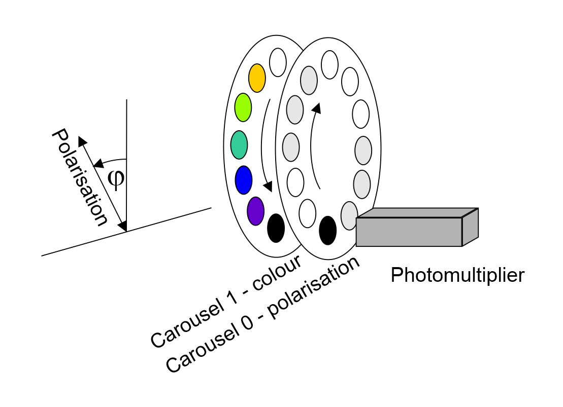
Filter mounting:
Carousel 1 (front, colors): 0 - closed, 1 - 400 nm, 2 - 450 nm, 3 - 500 nm, 4 - 550 nm, 5 - 600 nm, 6 - open, 7 - 650 nm, 8 - 700 nm , 9 - 750 nm, 10 - 800 nm, 11 - 850 nm
Carousel 0 (rear, polarization): 0 - closed, 1 - 0 & deg ;, 2 - 30 & deg ;, 3 - 60 & deg ;, 4 - open, 5 - open, 6 - open, 7 - 90 & deg ;, 8 - 120 & deg ;, 9 - 150 & deg ;, 10 - open, 11 - open
Update 2023: We developed also a modified version of the device containing filters with 10 nm bandwidth for wavelenghths 350 nm, 400 nm, ..., 800 nm. The use of these narrow-band filters makes it possible to consider the measured light as monochromatic, which greatly simplifies the interpretation of the measurements. Their disadvantage is the smaller amount of transmitted light and also the fact that the filters do not continuously cover the entire visible spectrum.
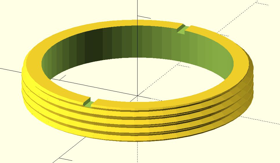
To pinpoint the position of the filters, we use a ring with holes and a photocell , one of the holes is longer, which allows it to be identified.
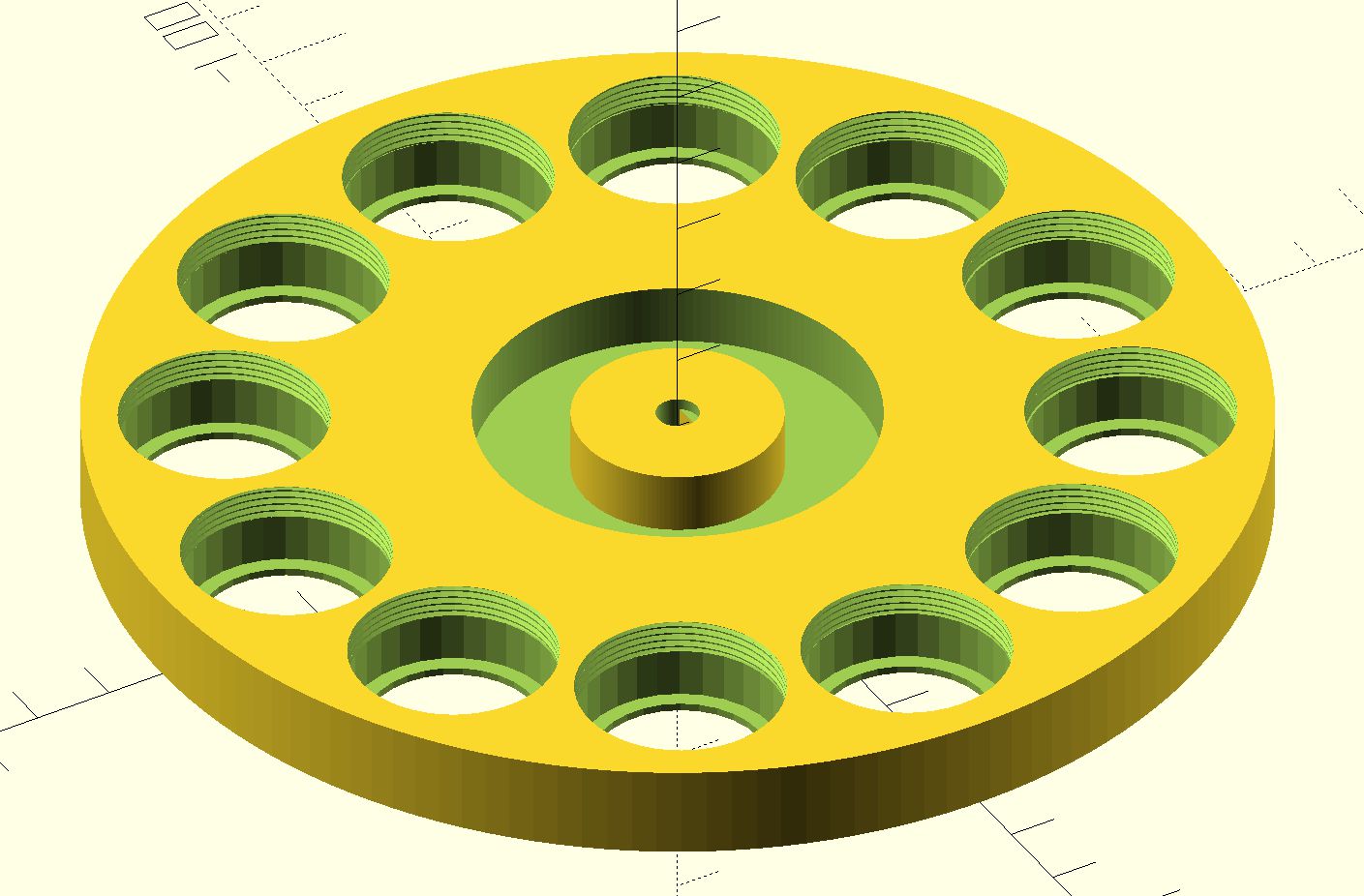
The filters are fastened with a nut, which is completely sunk into the carousel when tightened.
Half of the carousel with the case is in the following pictures:
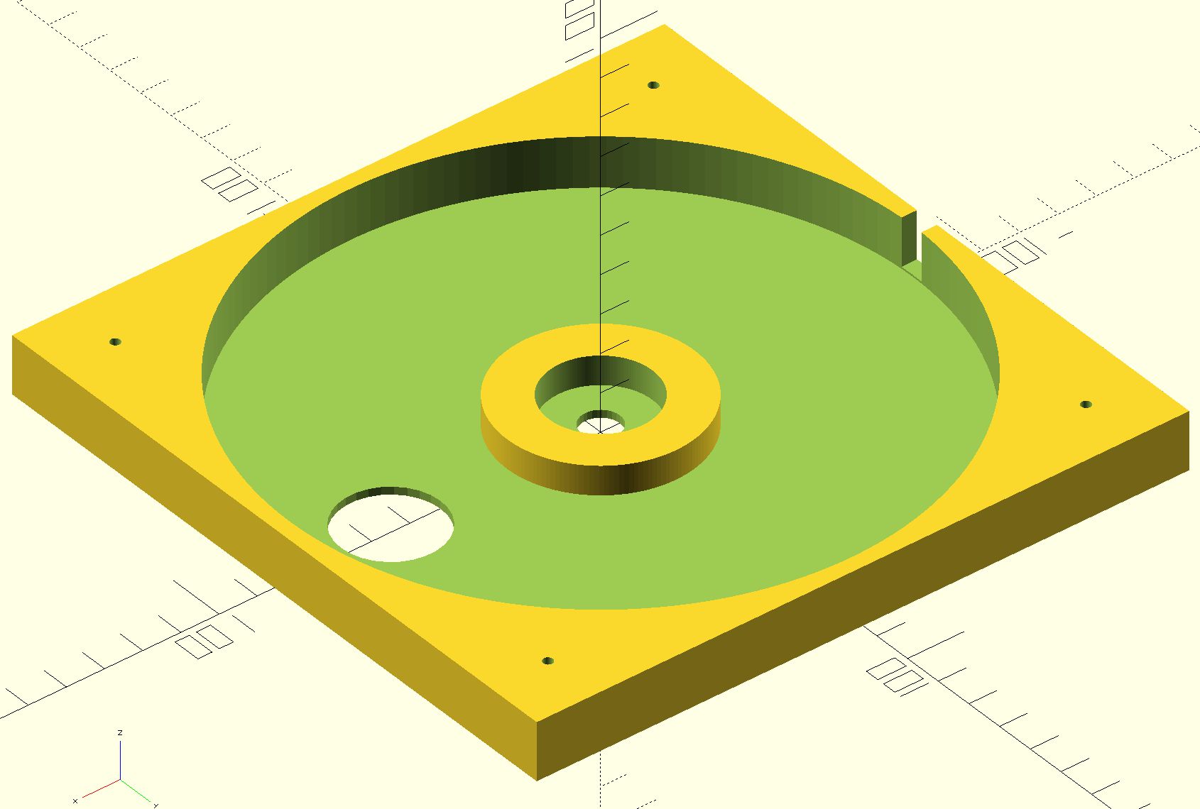
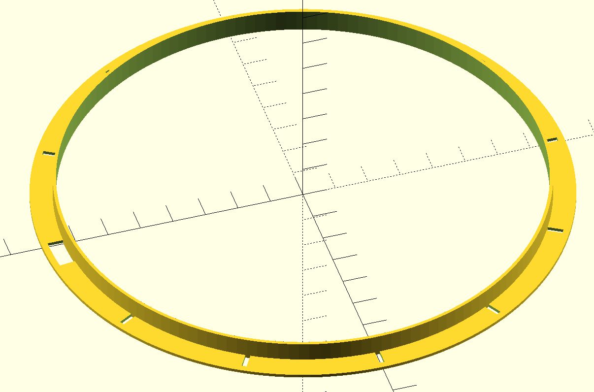
The photocell is inserted into the hole in the carousel housing and detects the holes in the ring on the carousel. Since we are measuring in the dark and the photogate is close to the input of the photomultiplier, the photogate can be switched on and off with a signal on the Arduino pin. We measure the photocell signal using the analog input of the Arduino, which allows us to flexibly set the reference level.
We rotate the carousels usingstepper motors. Since the filters are quite heavy and do not need to be moved very fast, we used stepper motor module with gearbox . The controllers of the two carousel motors are connected directly to the eight Arduino output pins. Due to the large weight of the filters and the play of the gears in the gearbox it was important to set the level of friction correctly. We achieved this by placing a thin plastic disk between the carousels, which we had previously bent slightly into a "U". The disc thus serves as a flexible pressure element to ensure proper friction. We solved the rest of the carousel inertia problems by software. In the final version, we achieved 80,000 error-free filter changes during testing (then we ended the test).
The lens and the box
We designed the box for 3D printing. For better access when installing the modules, the rear wall will be removable in the next version. Box view:
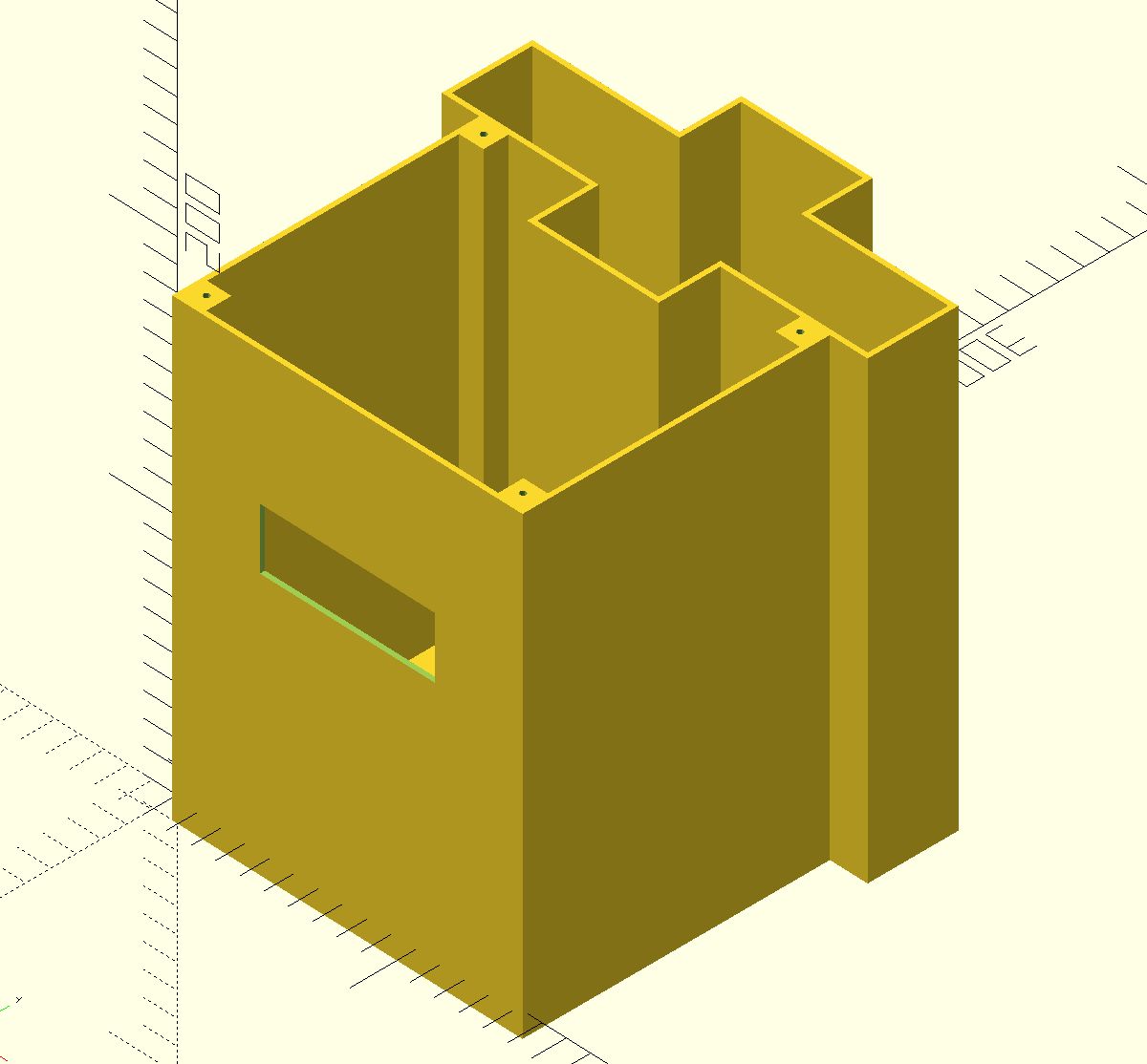

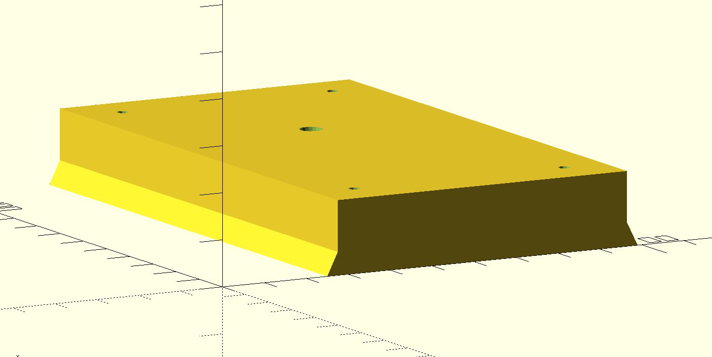
The box includes a cover and an interface for mounting the box to iPANO mount:
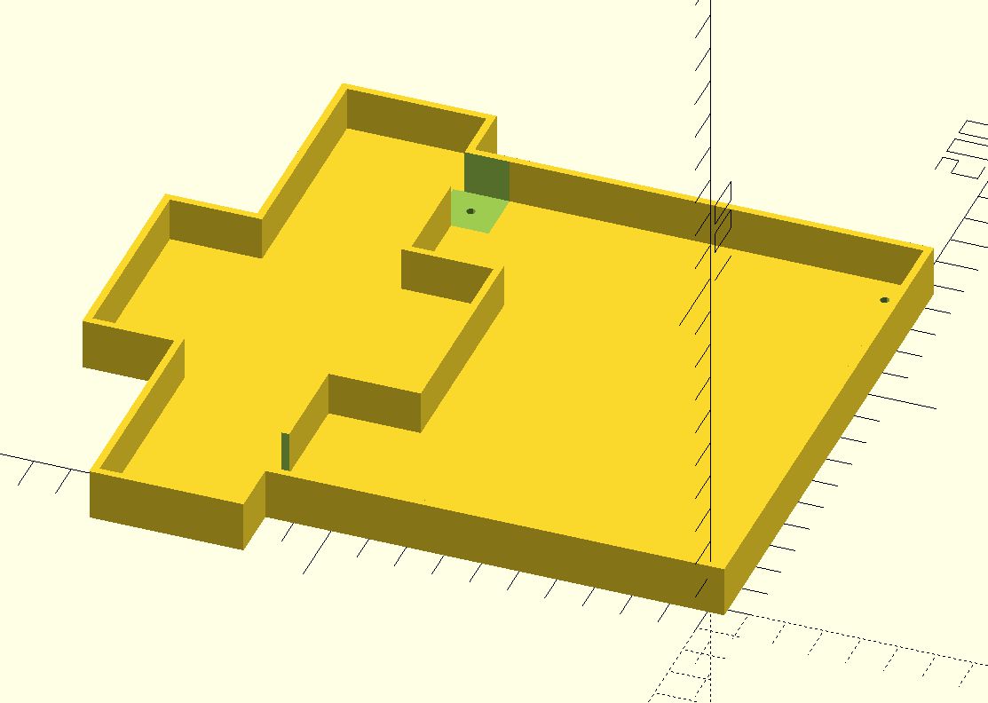
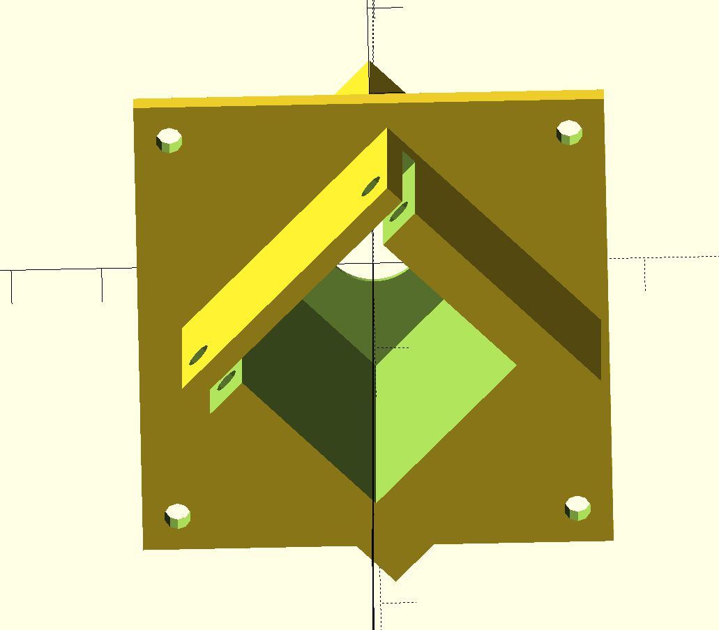
To hold the photomultiplier module, a holder is attached to the inside of the box:
The lens housing is quite complicated. It consists of a lens with a focal length of 50 mm, which concentrates the light on a photomultiplier. In front of the lens is a set of apertures defining a field of view of about 10 degrees and preventing the reflection of "side" light into the photomultiplier. Last but not least the apertures serve as a shield agains dew drops. The lens consists from smaller parts (lens, aperture and dividers) that are inserted into the body of the lens and fixed with a nut) so that the lens and apertures can be easily optimized:

ARDUINO-based control system and communication with PC
To control the entire system, we used the Arduino UNO microcomputer module, supplemented by standard modules:
- 16-bit A/D converter module with ADS1115 and I2C bus. We set the preamplifier gain to 1 (+/- 4.096 V), the signal from the photomultiplier we measure between inputs A0 and A1. We also measure the control voltage (the sensitivity of the photomultiplier) at input A2. The converter includes a temperature compensated reference voltage.
- 12-bit D/A converter module with MCP4725 and I2C bus. The converter is complemented by a simple voltage divider to adjust the output voltage from 5 V to 1.15 V according to the requirements of the photomultiplier. The stabilized + 5V source is used as a power supply of the module, which acts also as the reference voltage for this module. Since the stabilized + 5V source does not meet our requirements for thermal stability (we need change less than 1 mV when the temperature changes approx. 10 degrees), the voltage from the converter is measured by an accurate 16-bit converter.
- Linear stabilizer + (7.5-20V) / + 5V with LM7805. This module has a Grätz bridge at the entrance. Since one of the inputs of the bridge is in our case short-circuited with the (-) - output (both are connected to GND), the bridge no longer has a rectifying function, but acts as a reverse polarity protection (shortcuts the power supply, which must have current overload protection). We protect the electronics against accidental polarity reversal by a protection diode placed between the 9V source and the measuring system.
- LCD display 16x2 characters (blue) with I2C bus module.
- Digital thermometer Dallas with One-Wire line. Just connect a 5.1k pull-up resistor to the chip between VDD and DATA and thermometer can communicate with the Arduino.
- Converter module + 5V / -5V with charge pump LMC7660 (we actually used the equivalent ICL7660ACPA due to availability). We made this module ourselves, as the finished module with these features was not offered by Slovak sellers.
- Update 2023: Heating module with USB load 12V/15W controlled by the IRF520 module. The load is connected directly to the 12V battery, the current is set to 1.25A (15W).
The overall module interconnection scheme is on this link .
We have developed the command set for communication between PC and Arduino via a serial line. We decided for commands of a fixed length of 8 bytes,
which made it possible to ignore any other bytes received. The communication is thus independent of the setting of the terminating characters. Control philosophy
is such that the measuring system waits for the arrival of a command. After the arrival, the command is executed and the execution is confirmed (again with an 8-byte sequence).
Commands include setting of any filter from the carousel, initializing the carousel (resetting and covering the input to the photomultiplier),
setting the control voltage of the photomultiplier, measuring the signal from the photomultiplier, setting the number of measurements to be averaged, adjusting the brightness of the display
and setting the minimum allowed temperature in the case.
The complete set of commands is on this link .
The complete Arduino program listing (measuring head firmware) is on this link .
General view of the complete sky-scanner on the iPANO assembly and in the transport case:
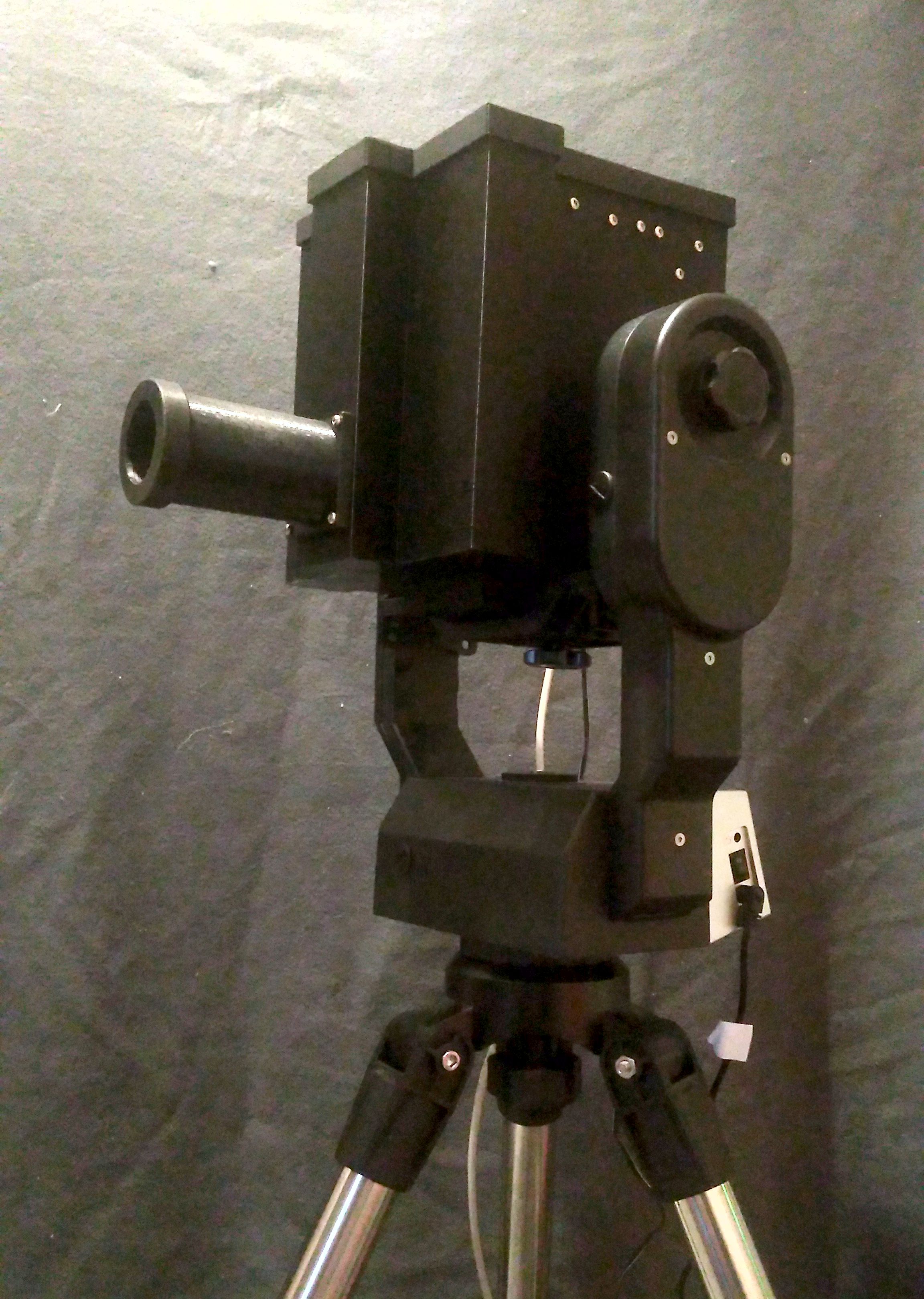
![]()
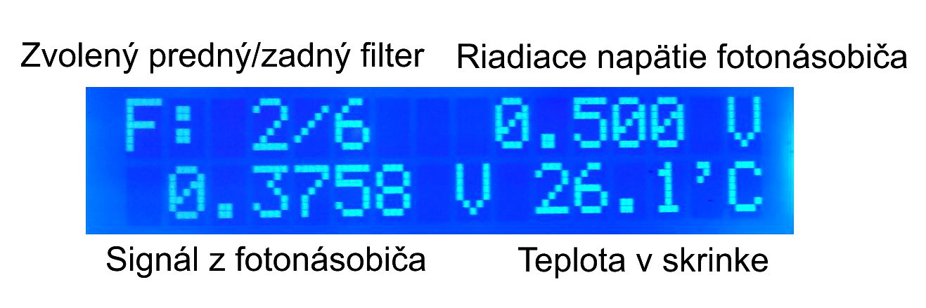
In the "waiting" state, the display shows the selected filters, the current values of the control voltage of the photomultiplier (determines its sensitivity) and photomultiplier signal, and the temperature in the case:
Results of test measurements
Using a point source (LED at a distance of 5 m), we measured the directional characteristics of the measuring head (field of view):
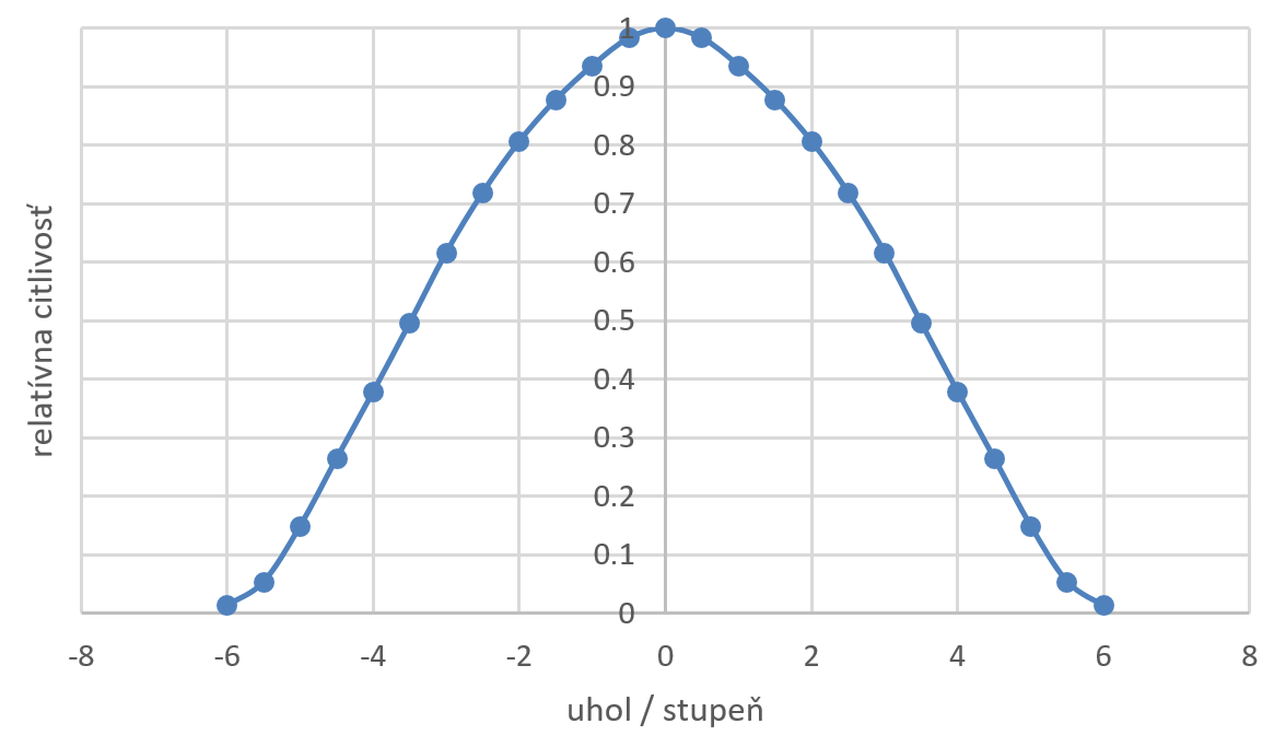
The field of view corresponds to the design of the apertures and the focal length of the lens, where we wanted to achieve an FOV of approximately 10 degrees. The measured half sensitivity is at an angle of +/- 3.5 degrees, the photomultiplier detects no signal after +/- 6 degrees,. We also verified that there is no measurable light reflection from the lens walls as the angle is further increased. This is important when monitoring light pollution close to the horizon, due to big contrast between lights from the city and the dark sky.
As part of the testing, we measured from the balcony in Devínská Nová Ves the spectrum of the night sky towards Vienna for elevations of 10 & deg; - 60 & deg (zenith angle 80 & deg; - 30 & deg;):
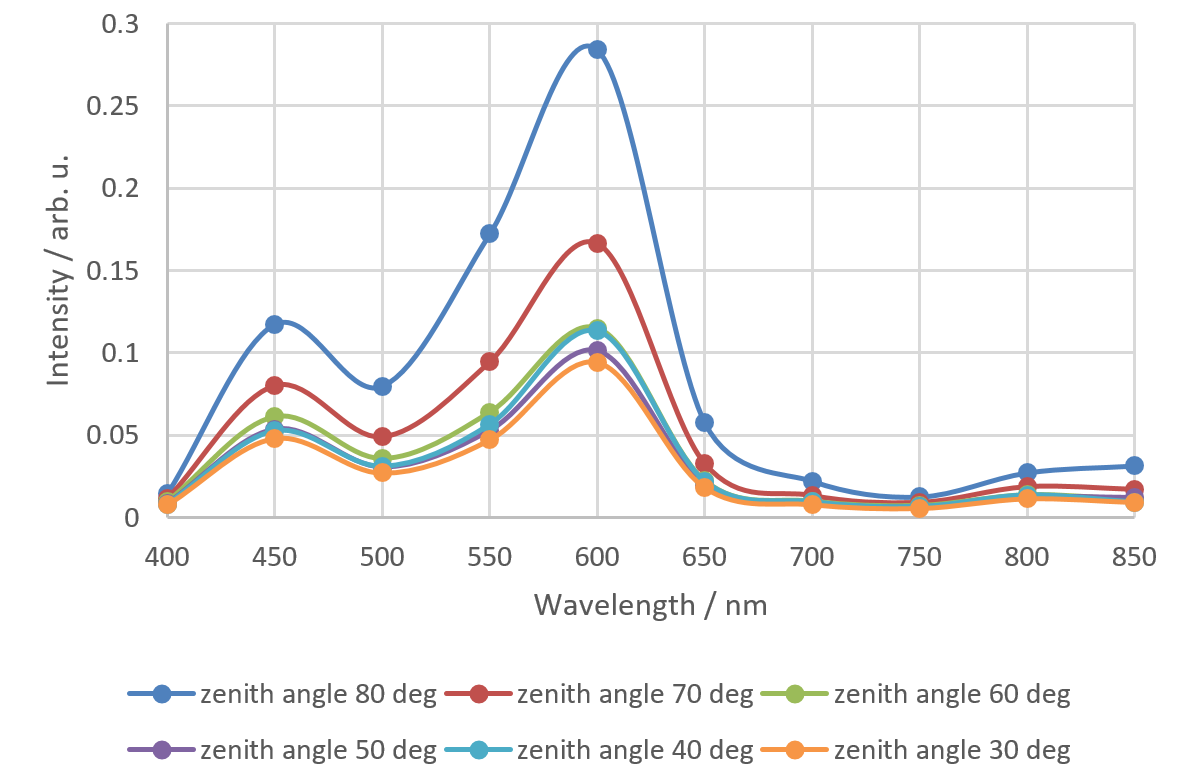
It can be clearly seen that at higher elevation angles (i.e. closer to the zenith) Rayleigh scattering is more important, so the amount of blue color is higher.
An important feature of polarizing filters is their ability to trap light when they are crossed. It determines the maximum degree of polarization, which we can measure with them. We therefore made measurements using our spectrometer , where we let the white light pass once through the parallel polarizers and once through the crossed ones. Measured degree of polarization (Imax-Imin) / (Imax + Imin):
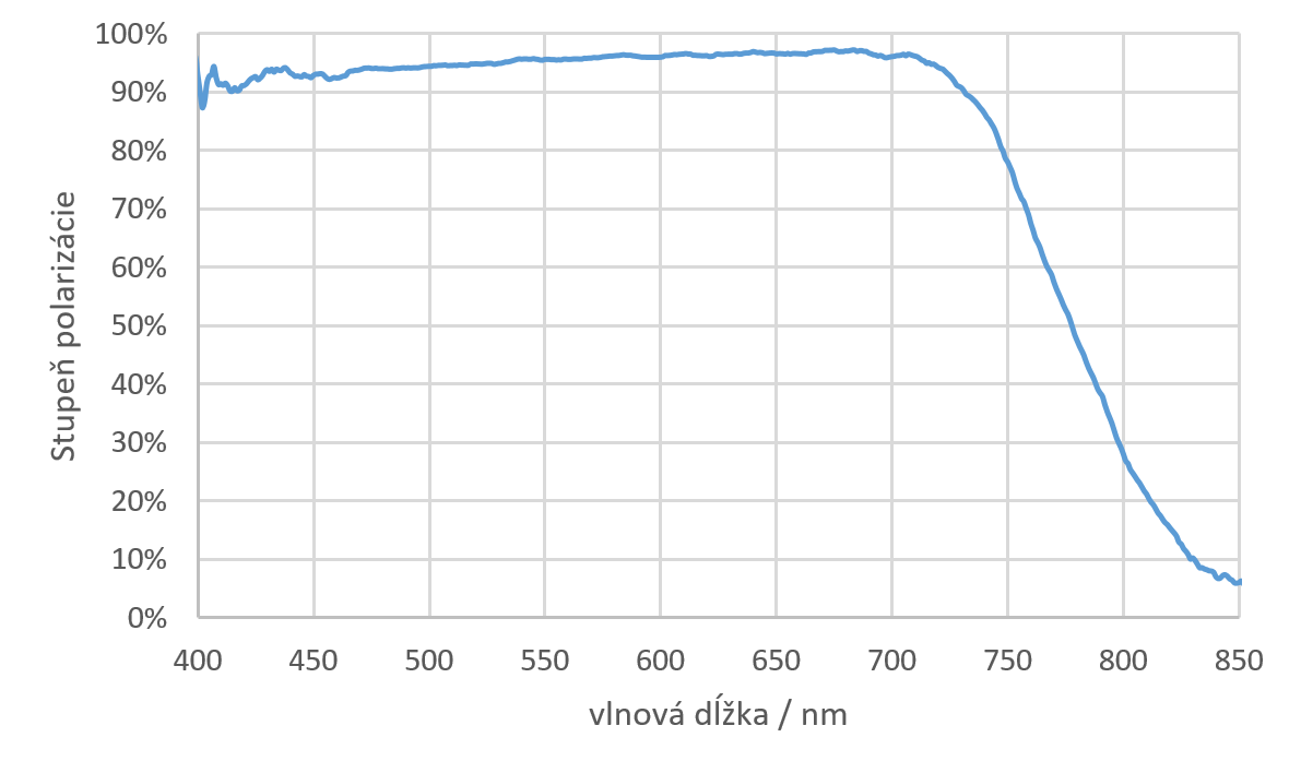
We see that our polarizing filters can be used in the range of 400 - 700 nm without any problems. However, since the degree of polarization of the skyglow of the night sky is usually less than 50%, they can also be used for this purpose even at a wavelength of 750 nm.
The next two images show an example of the sky signal over Vienna from DNV at a wavelength of 600 nm for different polarizer orientations (left) and dependence of the degree of polarization on the elevation angle (right):
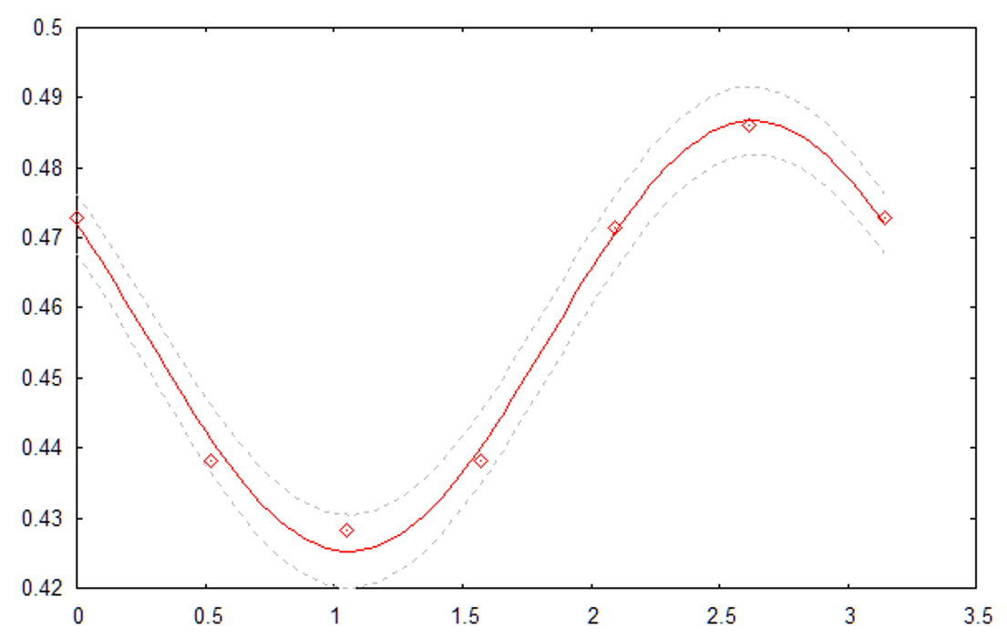

As expected, the degree of polarization is close to zero near the horizon (near the light source).
The heating module was tested at room temperature. After turning the heating permanently on, we observed the change in temperature inside the measuring head:
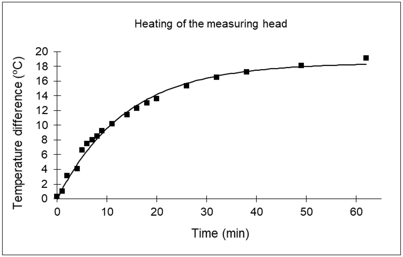
The temperature raised by 18.5 (+/-0.7) °C, so the minimal temperature of 5 °C required by the electronics can be maintained up to -10 °C without problems. If lower ambient temperature is required, we can use additional thermal insulation on top and sides of the measuring head.
The test measurement software written in Python is on this link . Similar to control program for iPANO, this program also allows recovery after accidentally breaking the USB connection between the PC and the measuring head.